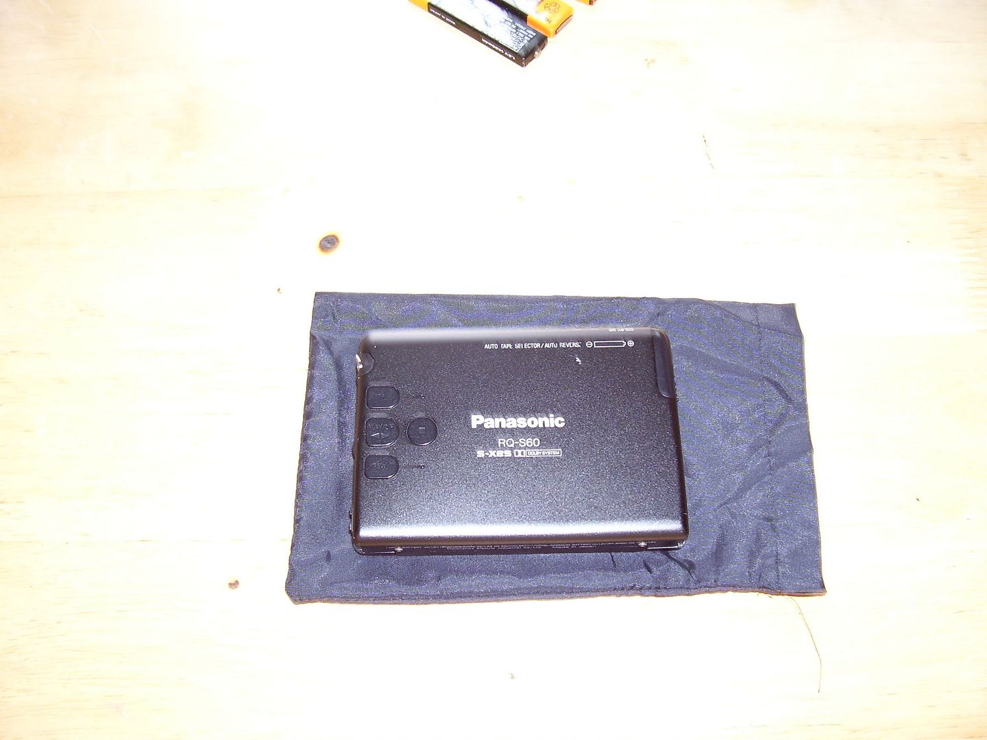
drmr2000 - 2010-03-15 12:37
Step one
Desolder relay points, battery terminal, and four servo motor points on PCB board, then removed three top screws holding PCB board in places also removed sensors screws for tape-in/tape type selector, then removed PCB board.
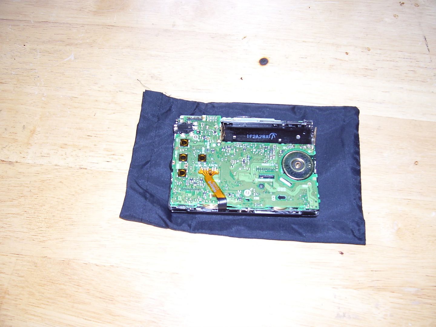
Step 2
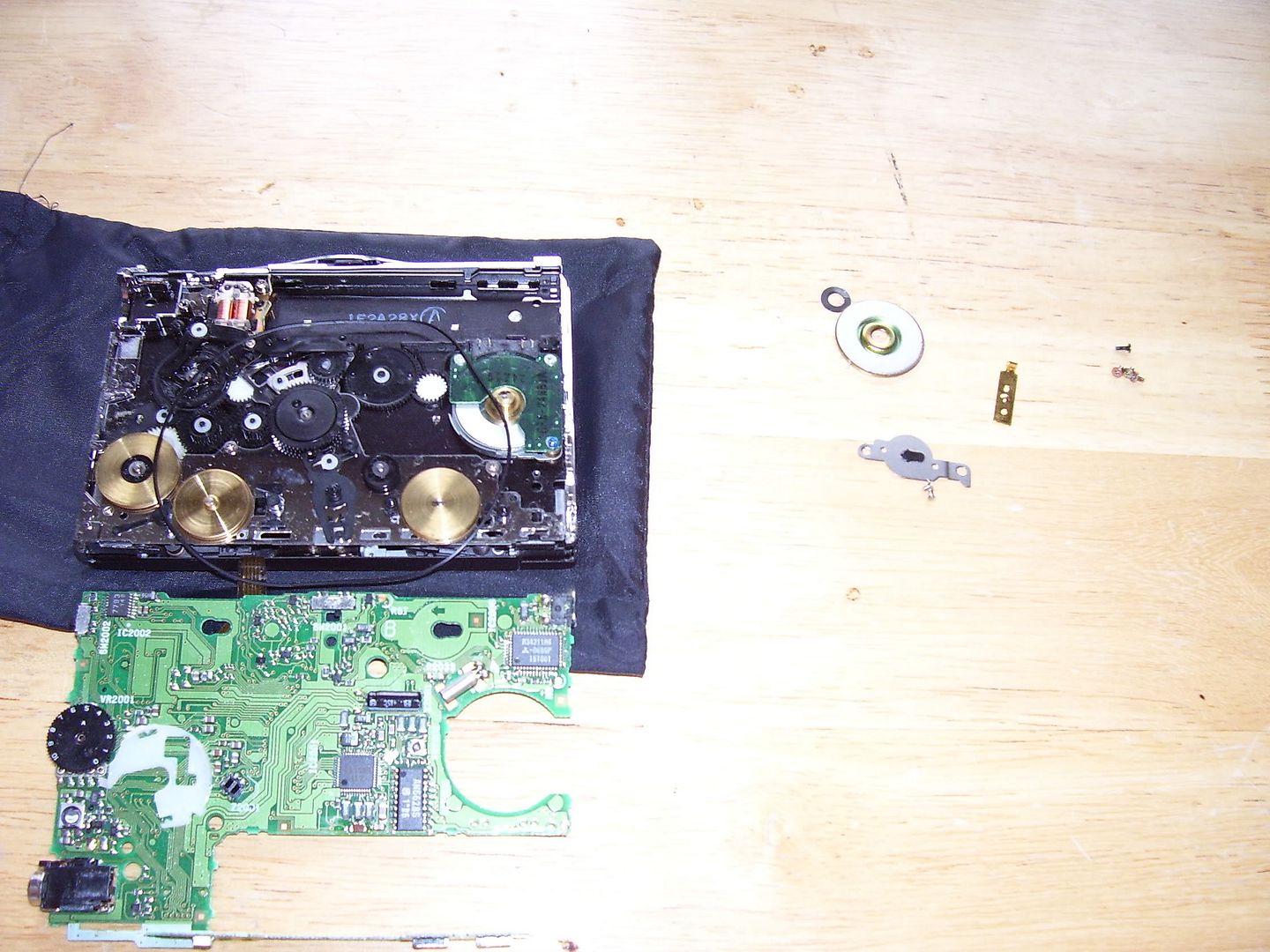
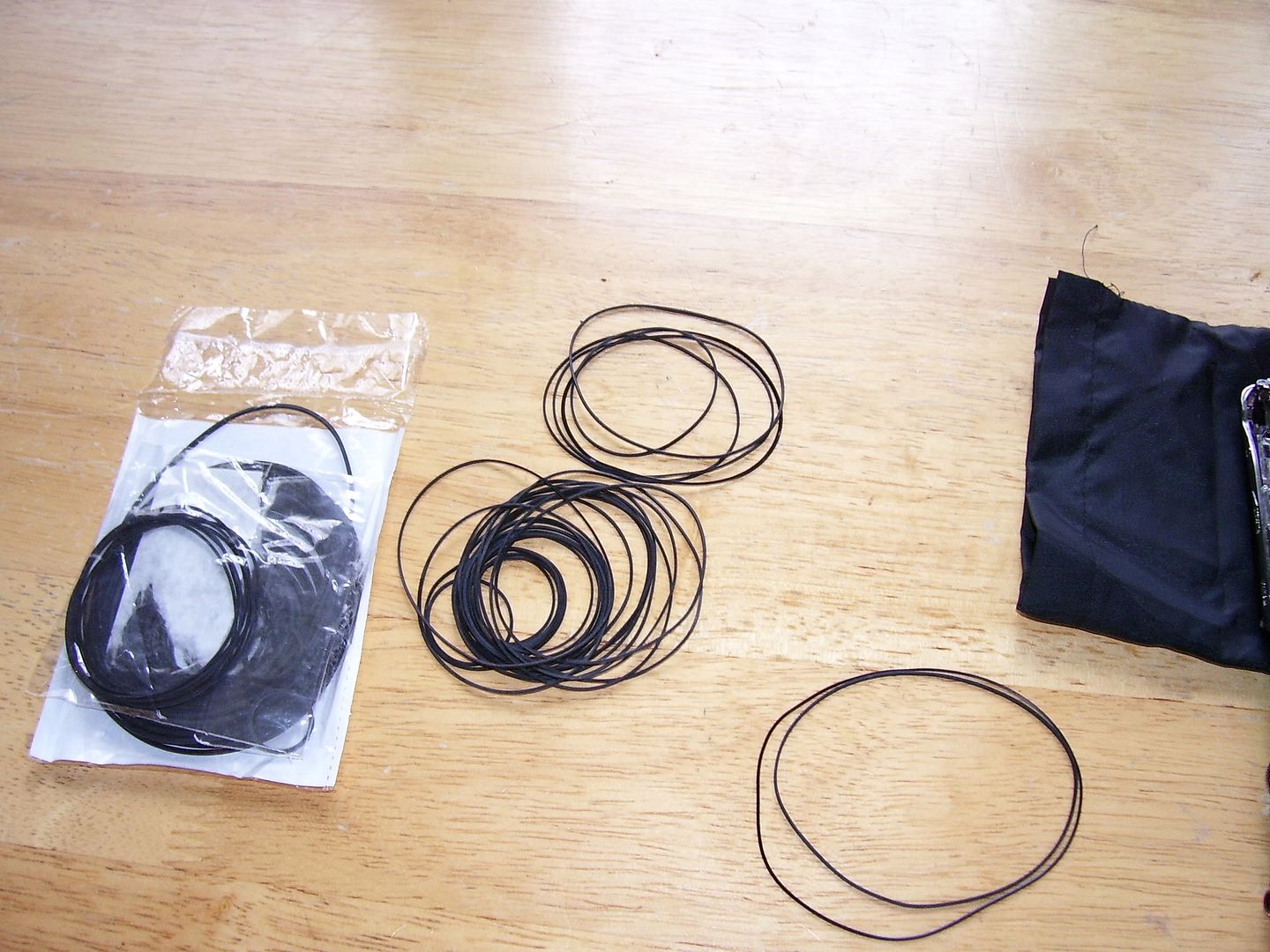
Once board removed, unscrew two screws holding capston plate in and removed top rotor. Installed belts same as in picture
Step three
Installed plate back on capston and top rotor also installed PCB board resolder all points servo motor, relay switch and battery terminal
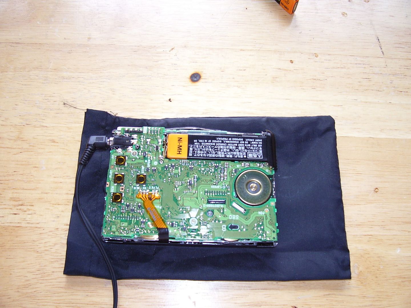
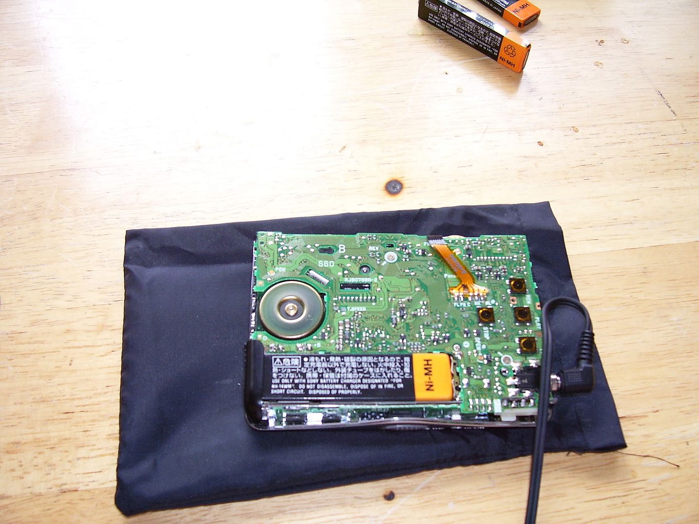
Step 4
Test unit makes sure it works before puting back cover.
